Using the General Modules in the Field Section
I. Launch the Field Section
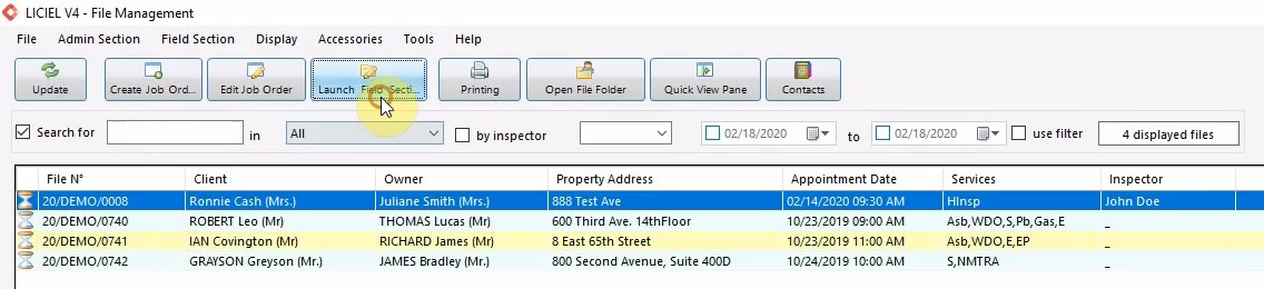
Once an order is created, we can select it from the list.
Click “Launch Field Section“ to get started.
II. Field Section Navigation
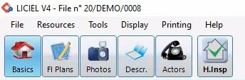
The Field Section Window has its own ribbon.
This ribbon displays all of the modules present in this job order.
All of the job orders begin with a few default modules.
On the left hand side we see “Basics”, “Floor Plans”, “Photos”, “Description”, and “Actors”, followed by any of the preselected inspections.
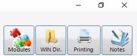
On the right hand side of the ribbon, we have “Modules”, “Printing”, and “Notes”.
You can navigate through each module by using the tabs at the top.
III. Pre-Load the Modules
Once the Field Section Window opens, we will pre-load all the modules.
This is to ensure that everything is loaded when we want to print.
To pre-load the modules, go to the “Basics” module, and select the “Client / Property” tab.
From here click the “Pre-Load All Jobs” button.
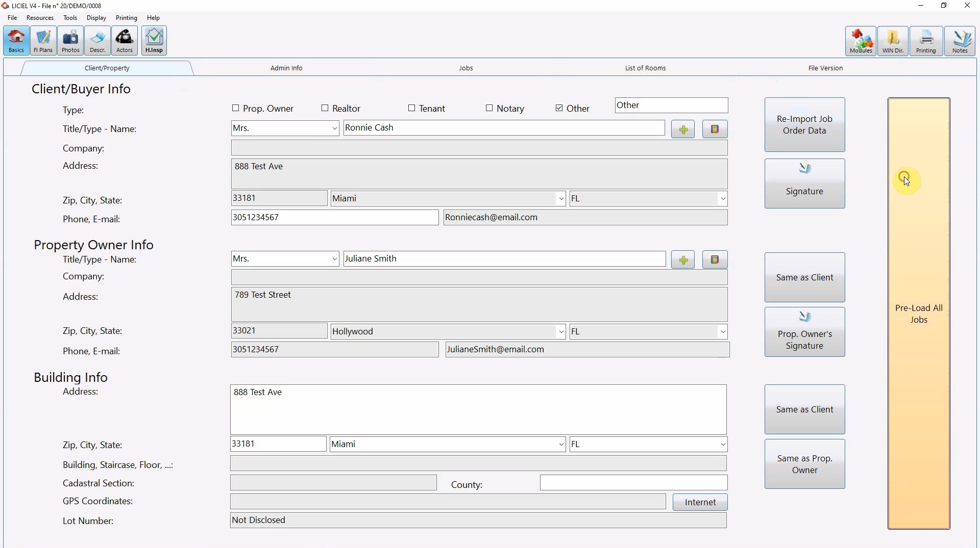
IV. The "Basics" Module
The “Basics” module also allows you to edit the information entered during order creation.
For example, the client information, property owner information, and the building info.
Click on the next tab to edit information about the property, tenant, or appointment date.
Notice that these are the same fields from the job order creation.
Moving to the third tab “Jobs”.
This tab allows you to control which inspections you will be performing and who will be performing them.
As you check inspections on and off, take a look at the ribbon.
When the Asbestos checkbox is checked, the Asbestos module is added to the ribbon.
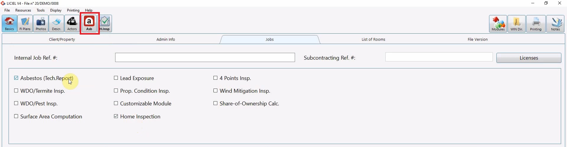
If Asbestos checkbox is unchecked, the Asbestos module is removed from the ribbon.
You can also assign or remove inspectors.
Click the “X” at the end of the row pertaining to the inspector you want to remove or click “Delete All” to delete all of the assigned inspectors.
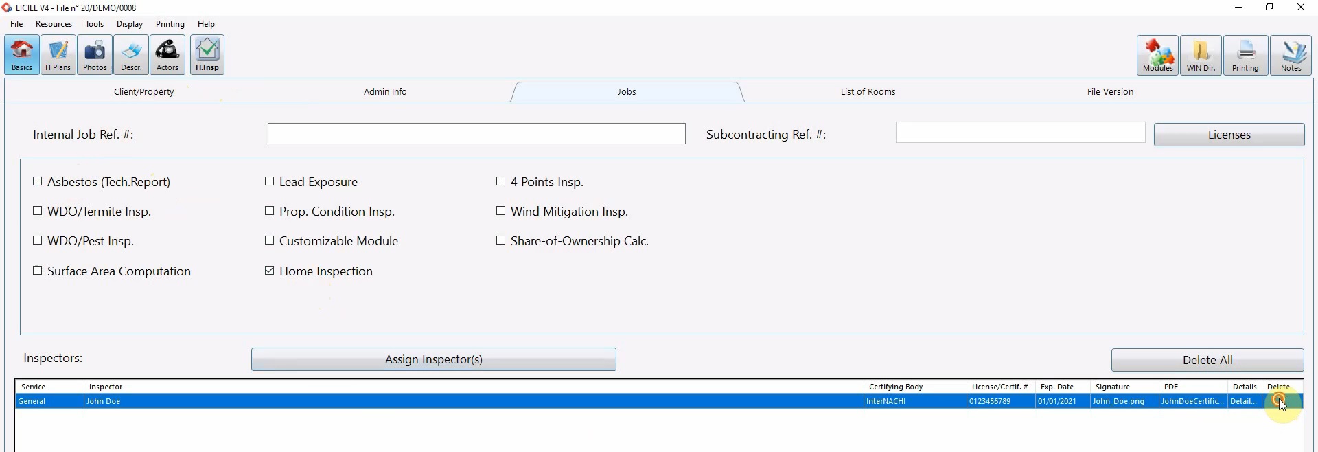
Click “Assign Inspectors”.
When the “Assigning Inspectors” popup opens, select an inspector from the drop down.
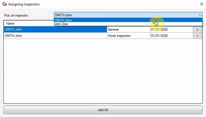
This will display all the certifications for that specific inspector.
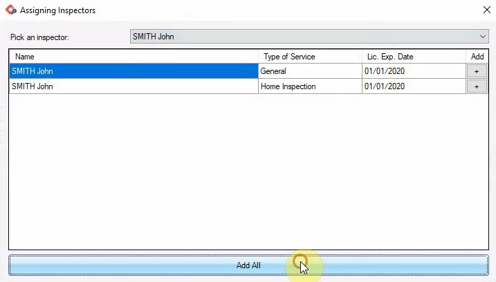
In some cases it might be necessary to include multiple certifications or multiple inspectors.
Add certifications individually by using the “Plus” sign or click “Add All” to add all the certifications for that inspector.
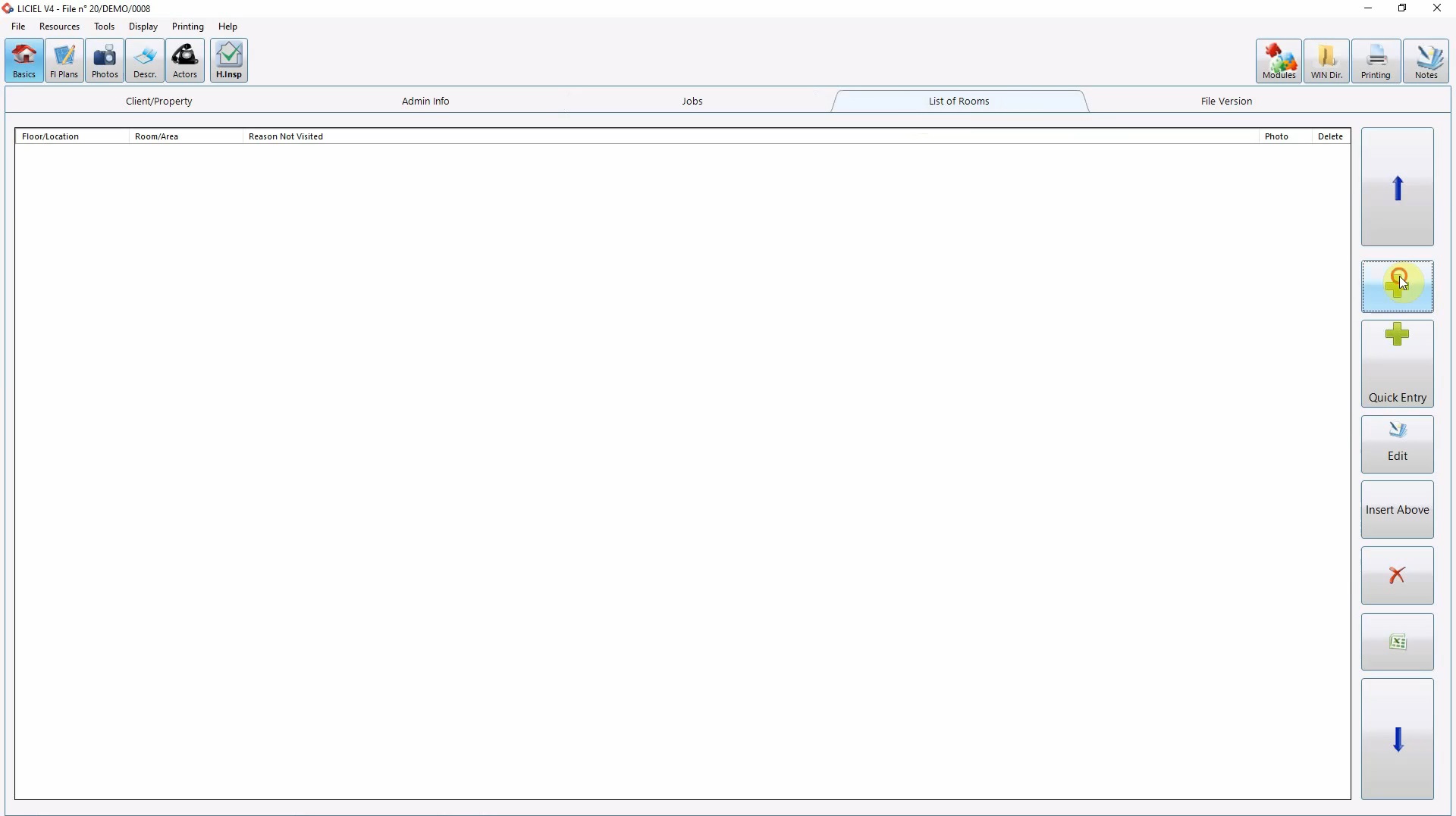
The 4th tab “List of Rooms” lets you add the rooms present.
Typically, these will be put in the same order that they will be visited in during the inspection appointment.
As you add pictures and comments you can specify the location by linking it to a specific room from this list.
Click the “Plus” sign to add a room.
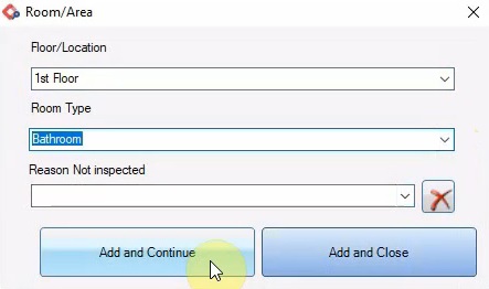
Specify the floor and room type manually or use the drop down to see the preset options.
If the room cannot be inspected, add the reason why.
Click "Add and Continue" or "Add and Close".
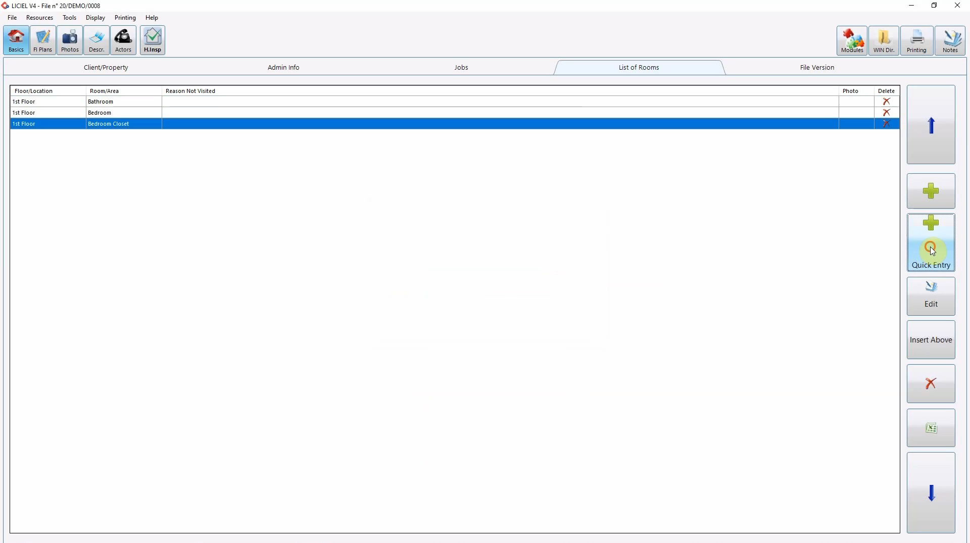
Rooms can also be added with the quick entry window.
Click the “Add Quick Entry” button.
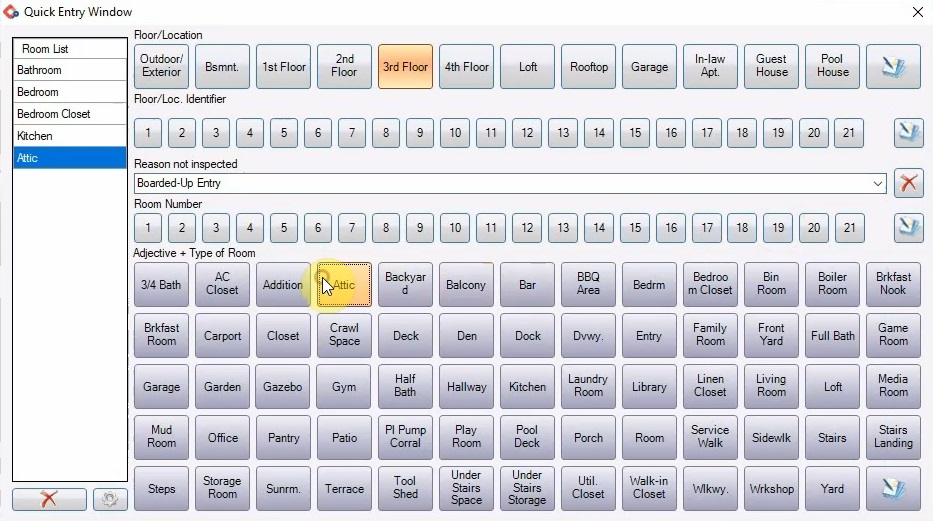
Select the floor, room number and type of room by using the dropdowns or click the notepad icon to enter the information manually.
If the room cannot be inspected, add the reason why.
One the type of room is selected, the room will be added to the list.
To remove a room, click on the room and then click the “X”.
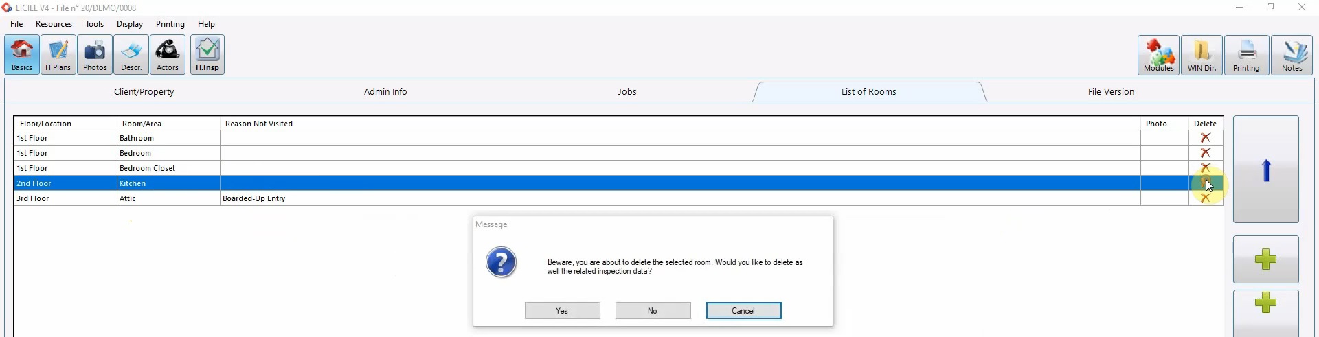
Use the arrows to arrange the order of the rooms.
In some instances like Asbestos, WDO (Wood Destroying Organism), and Mold, you might need to keep track of the multiple visits.
Use the last tab “File Version”.
Click the “Plus” sign to add a record of the file version and it's details.
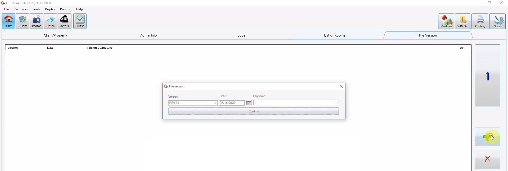
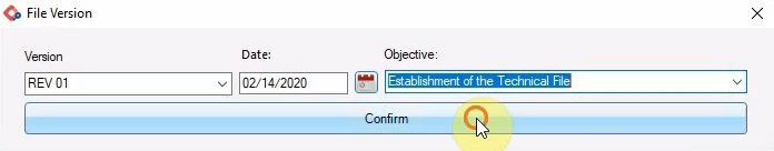
Select or enter the revision number and objective.
Specify a date and click “Confirm” to add it the list of versions.
V. The "Floor Plan" Module
Next up is the “Floor Plan” module.
From the ribbon, click “Floor Plans”.
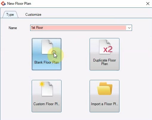
To create a floor plan, click “New Floor Plan”.
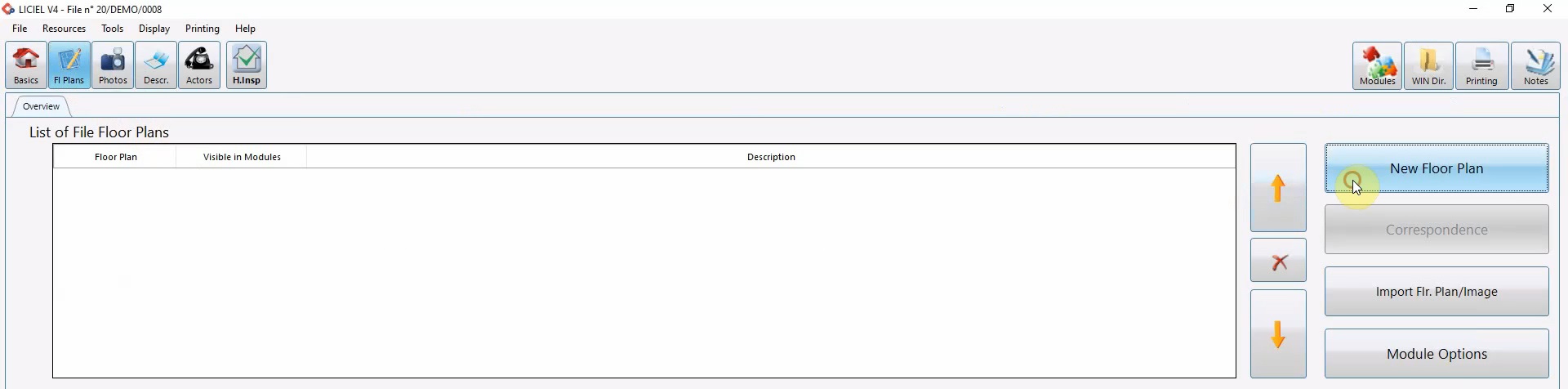
Enter a name and click “Blank Floor Plan”.
Once the floor plan grid is visible, begin using the drawing tools on the left to create the floor plan.
You can add exterior walls, interior walls, windows, doors, stairs, and more.
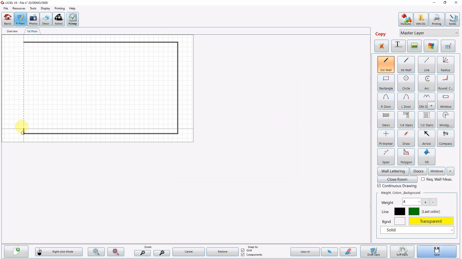
Items with a “Plus” sign have multiple options.
Toggle between the options using the “Plus” sign.
Use the drawing ribbon to move through the drawing tools.
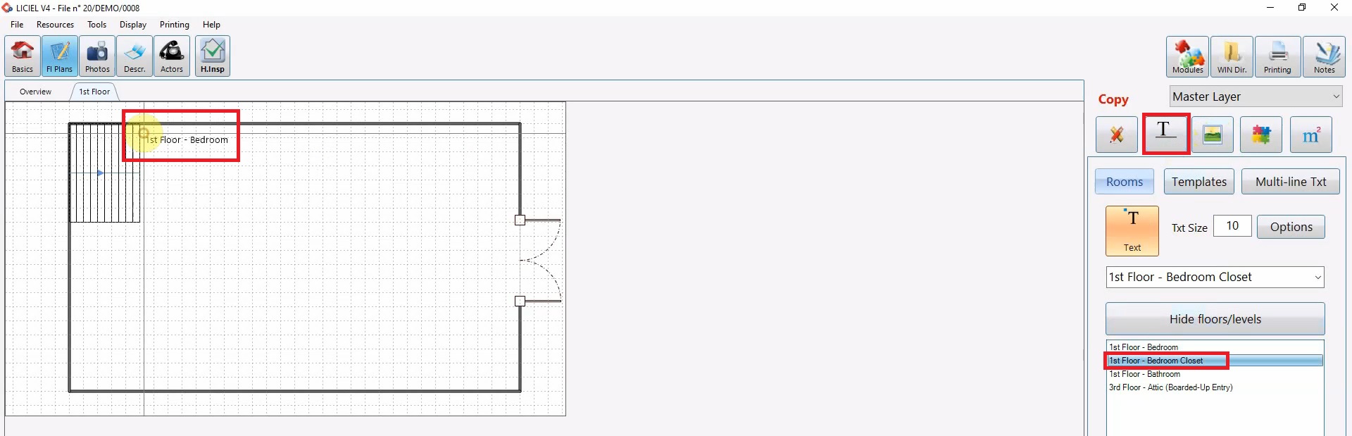
Add text like room type by clicking the “T” icon in the drawing ribbon.
Select the room you want to add. Use the “Text” icon to attach the text to your cursor. Text can also be entered manually.
Simply click on the grid to add the text.
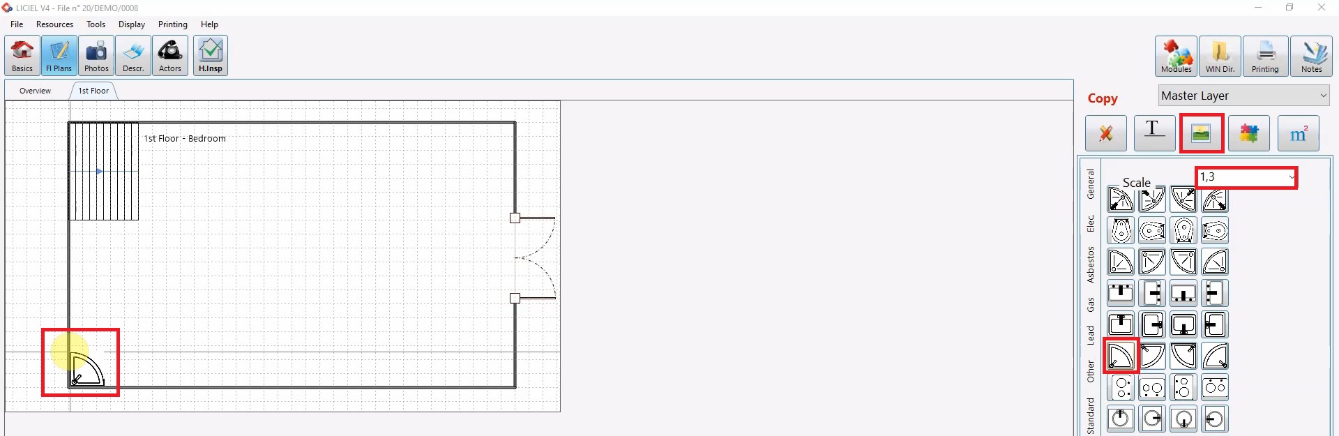
To add details like sinks, toilets, and custom images, click the “Picture” icon in the drawing ribbon.
Use the tabs on the sides to navigate to the “Features” tab.
Click an image, hover over the grid, and click when you are happy with the location.
To change the size of the image, use the scale drop down.
To remove anything that has been drawn, click the “Eraser”, hover over an item, and click to delete it.

When the floor plan is complete, click “Save”.

Use the “Overview” tab to view a preview of the plans added.
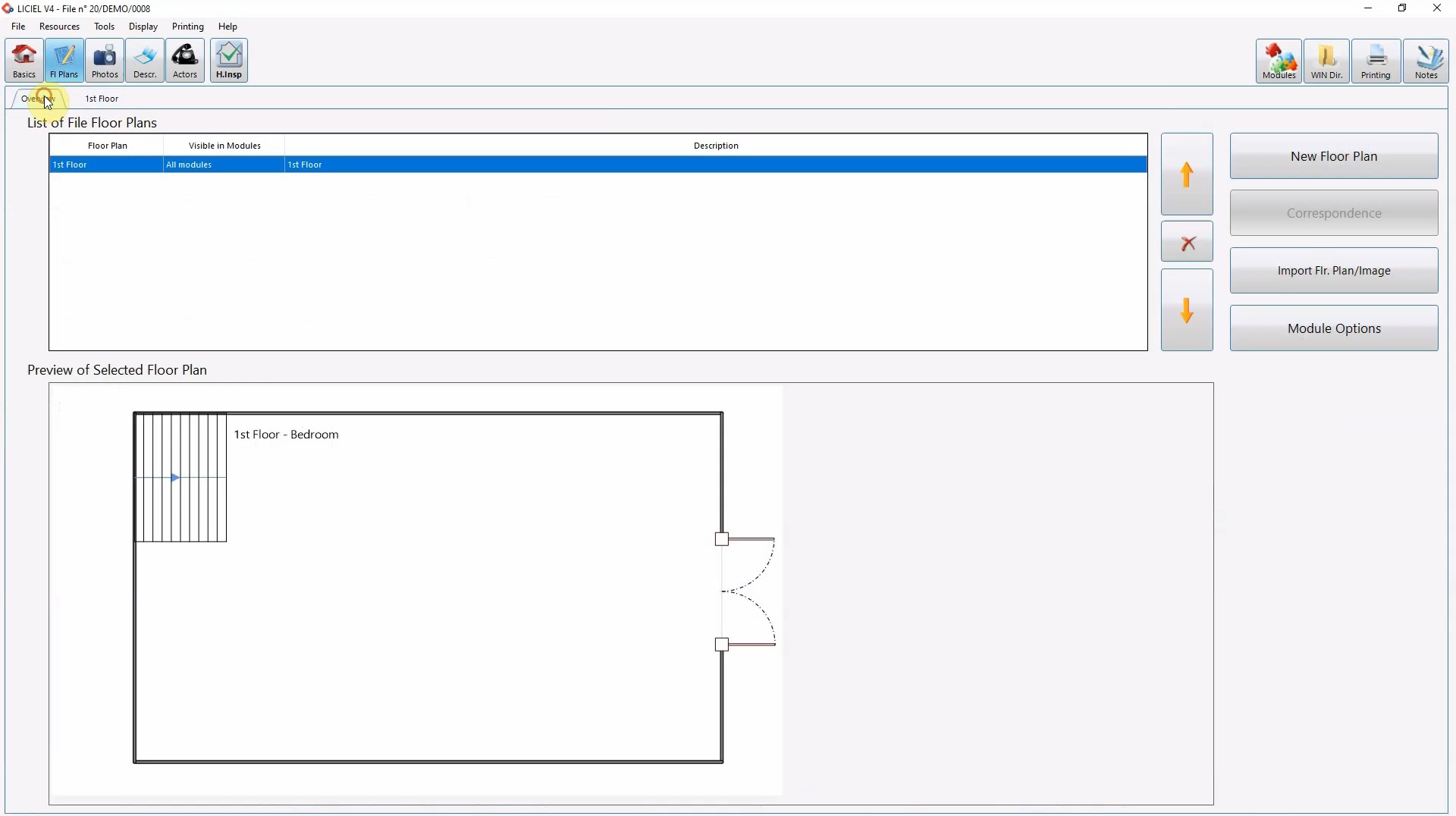
Use the “X” icon to delete a floor plan if necessary.
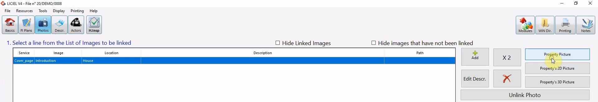
VI. The "Photos" Module
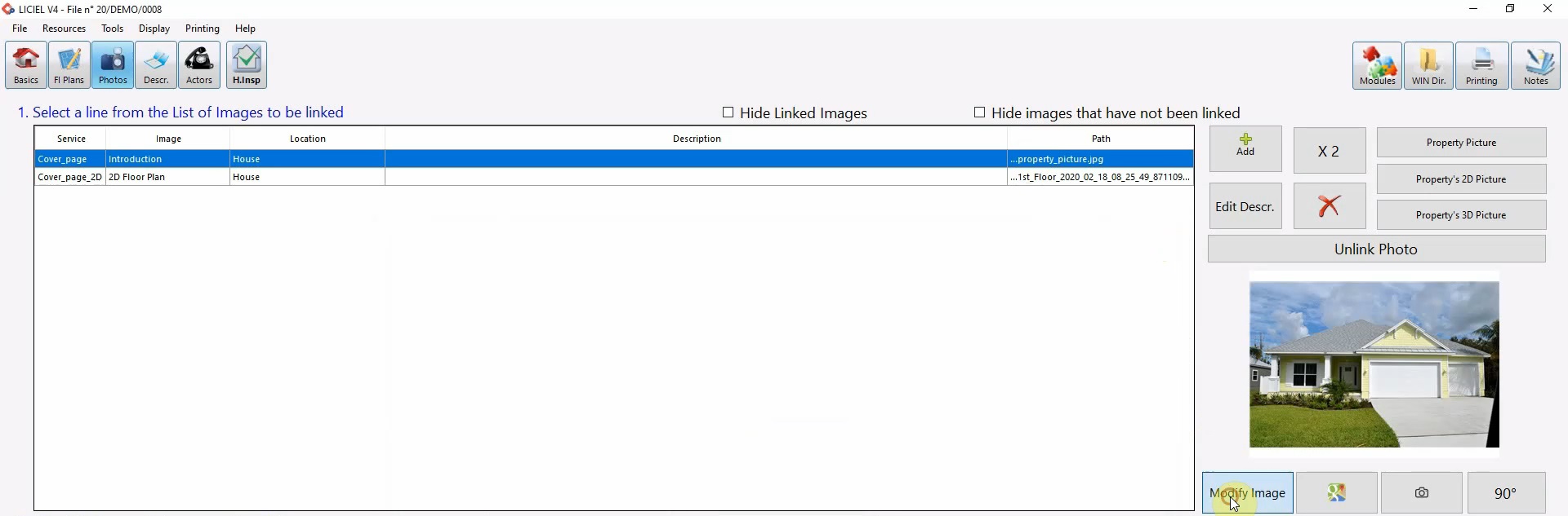
From the ribbon, click the “Photos” module.
Any photos added throughout the inspection will be added here.
Let’s add a property picture.
Click the “Property Picture” button.
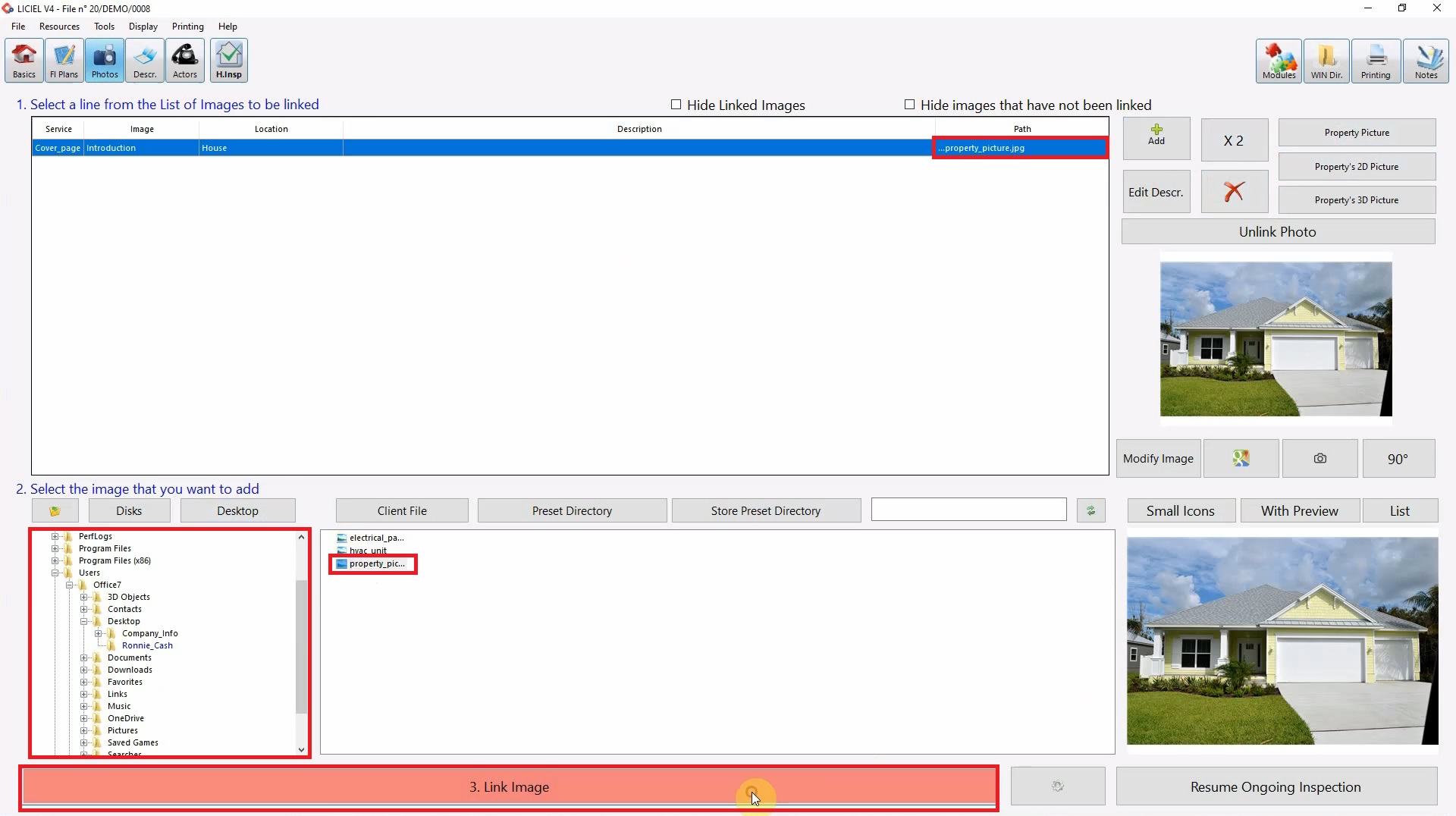
Now that we have the link, we are going to add the image.
Use the desktop button to view the desktop directory or use the directory on the left hand-side to find the image you want to link.
Select the image and click “Link Image”.
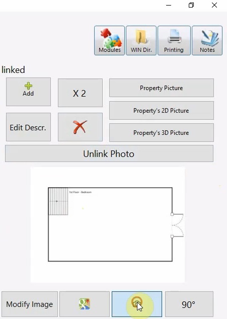
To add an image of the floor plan that was just created, click the “Property’s 2D Picture”.
Then, click the “Client File” button.
This is the folder for the current inspection.
When we created a floor plan, an image was saved to the picture folder.
Double click the “Plan” folder, select the floorplan, and click “Link” image.
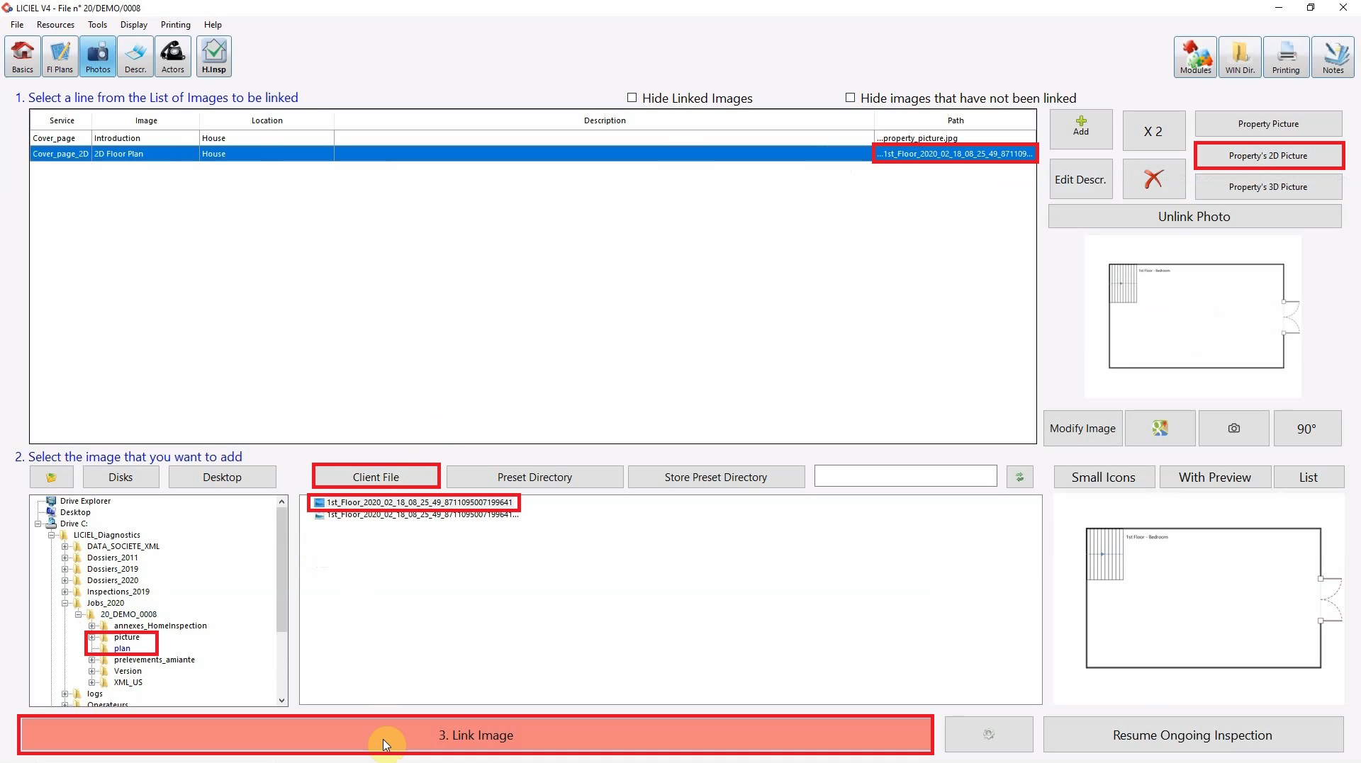
Unlink the image by clicking “Unlink Photo” or delete the image by clicking the “X” icon.
If you are using a tablet, click the “Photo” icon.
Select the “Take a Picture” tab to use your tablets camera.
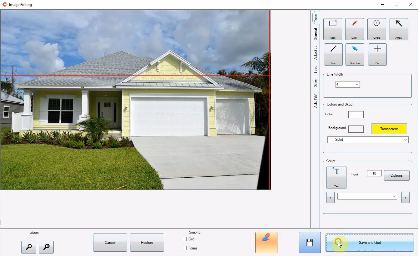
You can edit a linked image by selecting it from the list and then click “Modify” image.
Use the tools to draw on the image and click “Save and Quit” when you are satisfied with the modifications.
VII. The "Description" Module
Click the “Description” icon from the ribbon.
Use any of the methods to add a description for each room.
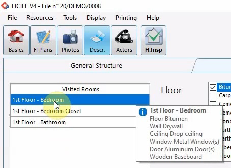
Click the “Simple Method #1” tab.
Select the room and check the appropriate descriptions.
The descriptions in the yellow boxes will be attached to the room when you click save.
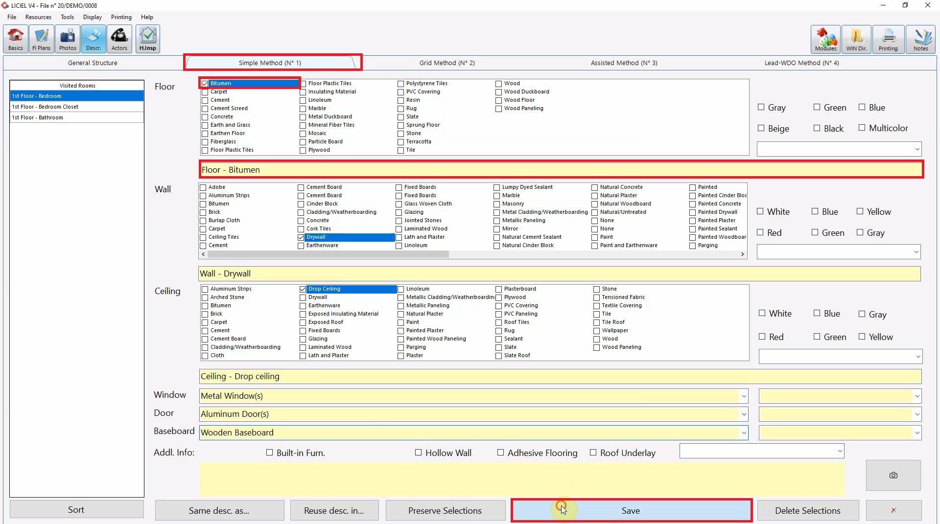
Hover over the room to see the description attached.
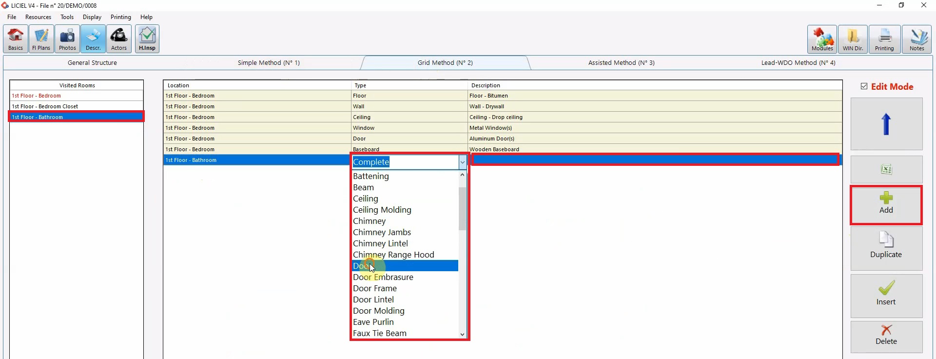
Click the “Grid Method #2” tab. Select the room to describe and click “Add”.
Click the “Type” cell to use the drop down or enter and item to be described.
Then, click the “Description” cell and use the dropdown to select a description or enter the description manually.
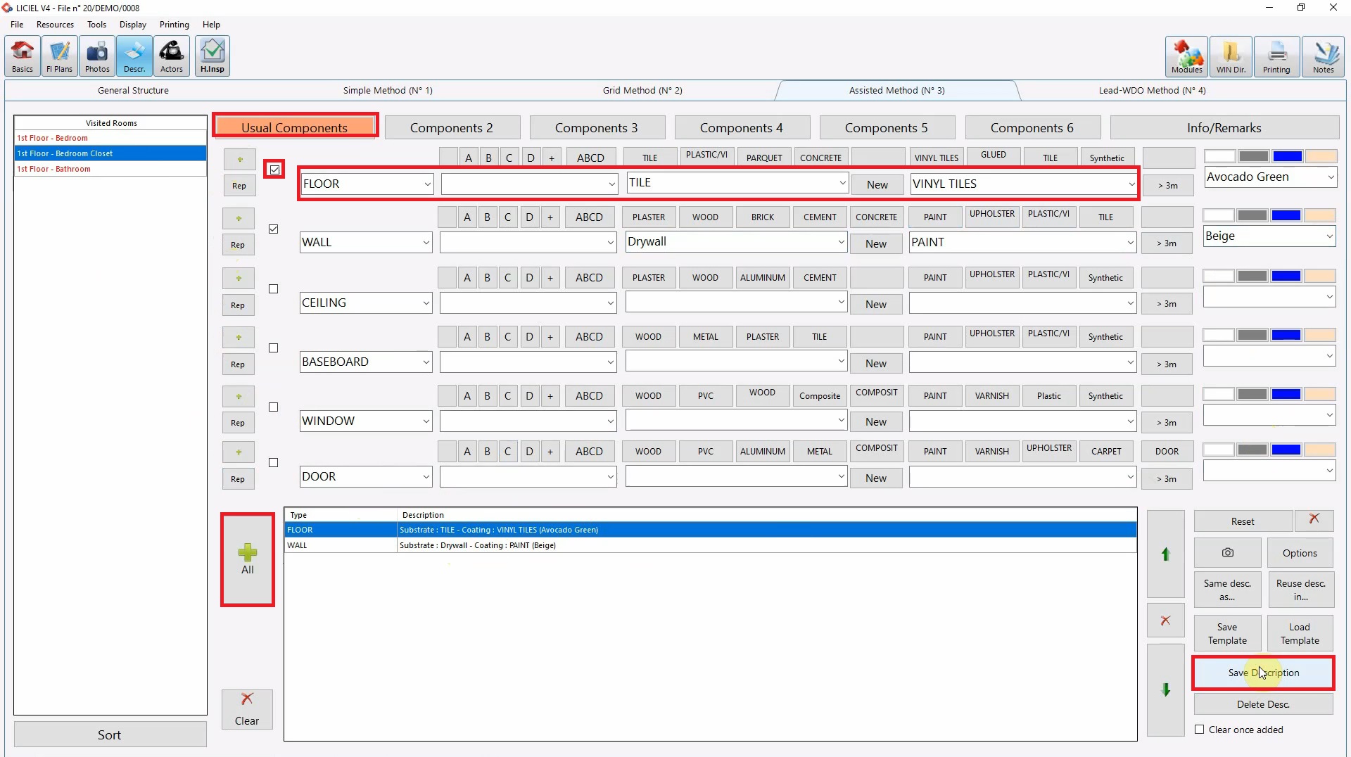
Click the “Assisted Method #3” tab.
Use the component buttons to navigate through the potential components of a room.
Use the dropdown to select the correct descriptions or enter them manually.
Then add each description individually using the small “Plus” sign or add all of the descriptions using the “All” button.
Click “Save Description” to save this description to the selected room.
VIII. The "Actors" Module
From the ribbon, select the “Actors” module.
This module allows you to specify any person present at the inspection.
Keep in mind that the special keys in the “Client” line and “Inspector” line will be replaced by the software with the appropriate Client name and Inspector name.
Check the checkboxes of anyone preset.
Now that we covered the basics of the “Field Section” we are ready to begin conducting an inspection.