|
|
Floor Plan Drafting/Sketching Module |

I. Introduction
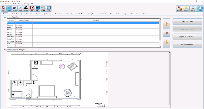
The Floor Plan Drafting/Sketching Module allows you to create sketches and floorplans to accompany your reports. This tool works alongside, and in sync, with your inspection work, allowing you to build up and embellish your floorplans as per your expertise. It also works in conjunction with the Surface Area Computing Module, allowing you to take measurements, and hence automatically creating the room floorplans that you will need to complete your job.
I.A Overview Tab
This tool allows to create or import your diagrams from your computer. It also allows you to associate the floorplans with their corresponding jobs, and access to the Options module, among other functions.
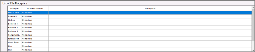
I.B List of Floorplans Section
The List of File Floorplans section allows you to access to all of the floorplans previously created or imported from your computer.
This section also offers you information about the sketche's names, the modules where they are visible, and their descriptions, if any.
I.C Buttons Section
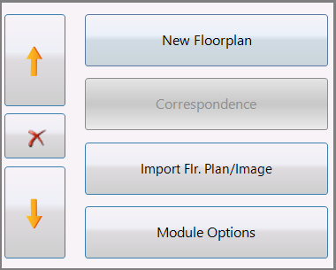
Use the following buttons to manage the sketches/floorplans.
to sort the List of File Floorplans as needed.
 to delete a selected sketch from the list.
 to guide you directly to the New Floorplan window (see below), which opens on the Type tab by default.
-
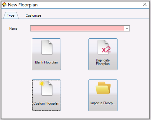
On the Type tab:
-
The Name drop-down menu allows you to select the title of your sketch or freely write it.
-
The
 button allows you to create a new diagram (see section " II.A Creating a Floorplan").
 -
The
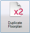 button allows you to copy the selected floorplan (see section " II.B Duplicating a Floorplan").
 -
The
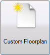 button takes you to the Customize tab, where you can personalize your sketches (see section " II.C Customizing a Floorplan").
Back on the Type tab.
-
The
 button allows you to upload diagrams from your computer (see section " II.D Importing a Floorplan").
- Back on the Buttons section:
 allows you to associate the selected floorplan with specific job(s).
 allows to import sketches/images from your computer (see section " II.D Importing a Floorplan").
 displays the Options menu:
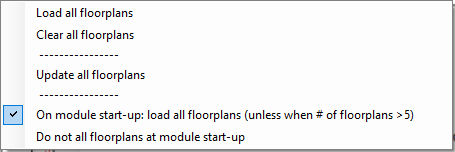 |
Load all floorplans - opens all sketches associated with the current file. On module start-up load all floorplans (unless when # of floorplans > 5) - opens all plans if there are more than five when starting up the module. Do not load all floorplans at module start-up - do not opens the plans when loading the module. |
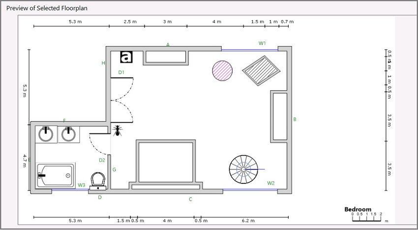
I.D Preview of Selected Floorplan Section
The Preview of Selected Floorplan section allows you to visualize an overview of the floorplan previously selected from the List of File Floorplans section.
II. Managing Floorplans
Note: The Floorplan Drafting/Sketching Module gives you the possibility of using a diagram, which could be considered as a base floorplan, and then make different layers depending on the inspection(s) that you are performing (see section "3 .G Base sub-tab").
II.A Creating a Floorplan
1. On the Overview tab, click on to display the New Floorplan window (shown above).
2. Select the title from the Name drop-down menu or create a new one to your liking.
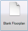
3. Click on the Blank Floorplan button to create a basic sketch.
The Drawing Window (shown below) will open for you to create the floorplan (see section "III. Working on your Floorplan" ).
II.B Duplicating a Floorplan
1. On the Overview tab, List of File Floorplans section, click to highlight the plan that you want to duplicate.
2. Click on to display the New Floorplan window, which opens on the Type tab by default.
3. Click on to save the plan in your computer.
The Drawing Window (shown below) will open for you to work on the duplicated floorplan as needed (see section "III. Working on your Floorplan").
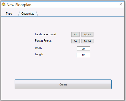
II.C Customizing a Floorplan
1. On the Overview tab, click on to display the New Floorplan window.
2. Select the title from the Name drop-down menu or create a new one to your liking.
3. Click on to open the Customize tab.
4. Complete the following fields:
- Landscape Format
- Portrait Format
- Width
- Length
5. Click on  to save your selections.
The Drawing Window (shown below) will open for you to create the customized floorplan (see section "III. Working on your Floorplan").
II.D Importing a Floorplan/an Image
1. On the Overview tab, click on to access to your LICIEL Diagnostics Plan's folder in your computer.
2. Select the desired floorplan/image and upload it.
The Drawing Window (shown below) will open for you to work on the imported floorplan/image as needed (see section "III. Working on your Floorplan").
Note: There is another method for you to import an sketch/image.
1. On the Overview tab, click on to display the New Floorplan window.
2. On the Type tab, click on to access to your LICIEL Diagnostics Plan's folder in your computer.
3. Select the desired floorplan/image and upload it.
The Drawing Window (shown below) will open for you to work on the imported floorplan/image as needed (see section "III. Working on your Floorplan").
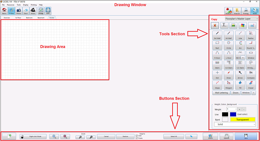
III. Working on a Floorplan
Whether you are creating a basic sketch or a customized floorplan, or duplicating or importing a diagram, the Drawing Window (see below) will open for you to work on your plan.
Use the Drawing Area to draw your sketch, and the Tools and Buttonssections to work on it.
Note: As explained in section "III.B Buttons Section", below, you can save your sketches by clicking on  , nevertheless, each time that you close the Drawing Window, the software will ask you to save the changes before quitting.
After saving them, all of the diagrams that you have created so far will automatically be stored on the File's Plan folder in your computer.
III.A Tools Section
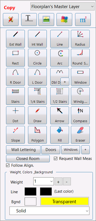
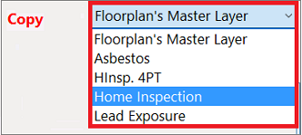
The Tools section includes the Copy drop-down menu (see below), which includes the Floorplan's Master Layer and the modules you have been working with.
 |
 The Tools section also includes five buttons that give you access to a number of very useful tools.
See a detailed explanation of each of these buttons below. |
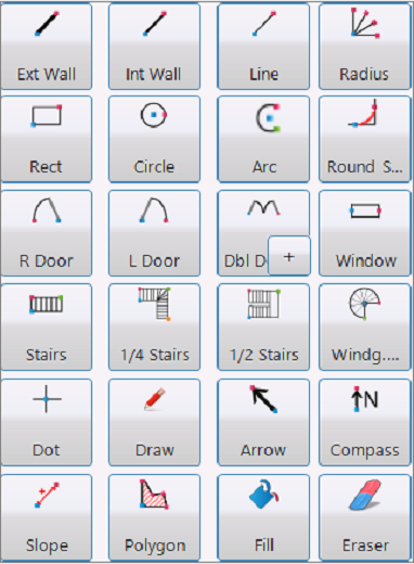
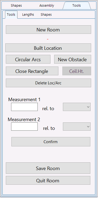
1. Tools Button
The  button allows you to choose your drawing and writing tools.
1.A Tools Section
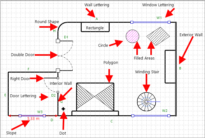
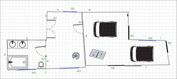
This section allows you to insert components into your floorplan and identify them (see the explanation and the example floorplans, below).
|
|
|
||||||||||||||||||||||||
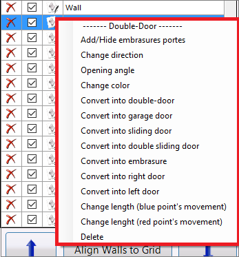
*To access different types of door (Sliding Door, Garage Door, Doorway, etc.), click on  at the corner of the Double Door button. at the corner of the Double Door button. |
|||||||||||||||||||||||||
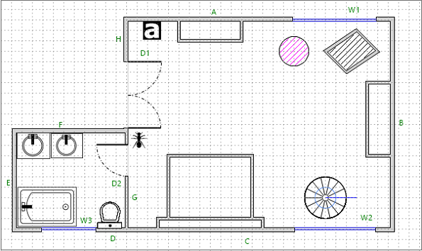
 allows you to identify the walls with letters (e. g., walls A, B, C, etc.). allows you to identify the walls with letters (e. g., walls A, B, C, etc.). |
|||||||||||||||||||||||||
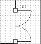
 allows you to identify the doors with letters and numbers (e. g., D1, D2, D3, etc.). allows you to identify the doors with letters and numbers (e. g., D1, D2, D3, etc.). |
|||||||||||||||||||||||||
 allows you to identify the windows in the same way (e. g., W1, W2, W3, etc.). allows you to identify the windows in the same way (e. g., W1, W2, W3, etc.). |
|||||||||||||||||||||||||
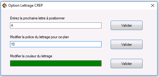
| displays the Font Options window for you to enter the next letter position and/or modify the font's size/color. |
|||||||||||||||||||||||||
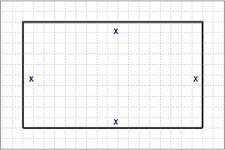
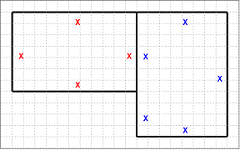
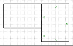
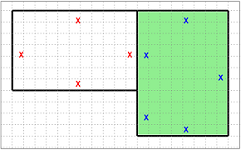
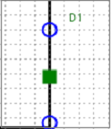
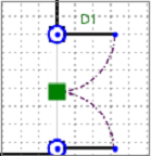
 only displays after clicking on Wall Lettering, Doors, Windows, and + buttons, and it is basically useful when you are working on a Lead Exposure Assessment diagram. only displays after clicking on Wall Lettering, Doors, Windows, and + buttons, and it is basically useful when you are working on a Lead Exposure Assessment diagram. This button inserts blue X on all of the walls (if you add one more room, all of the blue X on the first room will turn red and the X on the second one will display in blue to differentiate them). Then, if you place the cursor over any X, all of them will automatically convert into letters. And if you click on any letter, the selected room will turn green to serve you as a visual guide while you complete the sketch and enter data related with the job that you are working with, as shown in the following sequence. |
|||||||||||||||||||||||||
 allows you to close the room's sketch. Por example, let's say that you draw three exterior walls; then, if you click on this button, the software will add the final wall to complete the sketch. allows you to close the room's sketch. Por example, let's say that you draw three exterior walls; then, if you click on this button, the software will add the final wall to complete the sketch.This button displays only when working with wall buttons (Exterior Wall, Interior Wall, and Line). |
|||||||||||||||||||||||||
 allows you to insert the room's measures as you draw it. allows you to insert the room's measures as you draw it. This box displays only when working with wall buttons (Exterior Wall, Interior Wall, and Line). |
|||||||||||||||||||||||||
 allows you to draw consecutively. allows you to draw consecutively. Note: To make your draw step by step, uncheck this box or press the ESC key on your keyboard. This box displays only when working with wall buttons (Exterior Wall, Interior Wall, and Line). |
|||||||||||||||||||||||||
--->---> The following floorplan shows how some of the main components are inserted on the sketch. |
|||||||||||||||||||||||||
 |
|||||||||||||||||||||||||
1.A.1 Component Drafting Sequence
The tools buttons show different color points on their icons to help you identify the drafting sequence (see the example button, below).
- Blue indicates the start point
- Red indicates the second point
- Green indicates the third point
- Yellow indicates the last point
1.B Weight, Colors-Background Section
This section allows you to select the weight of the line and the background color (see the explanation and the example floorplan, below).
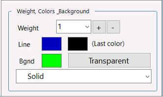
1.B.1 Selecting the Weight of the Line
To select this parameter use the Weight drop-down menu. You can also use the  buttons.
1.B.2 Selecting the Line Color
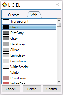
1. Click on the Line box on the left to open the Color Selector window (shown below).
If you want to use the last color utilized, then click on the Last Color box on the right.
2. Select a color on the Custom or Web tabs.
|
|
|
3. Click on  to save your selection.
If you need to clear it, click on  . To remove it, click on
  .
.
1.B.3 Selecting a Background Color
1. Click on the Bgnd box to open the Color Selector window.
2. Select a color on the Custom or Web tabs, as explained above.
3. Click on to save your selection. If you need to clear it, click on . To remove it, then click on .
Back on the Weight, Colors_Background section, if you do not want to use a background color, click on  .
.
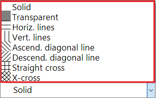
1.B.4 Selecting a Background
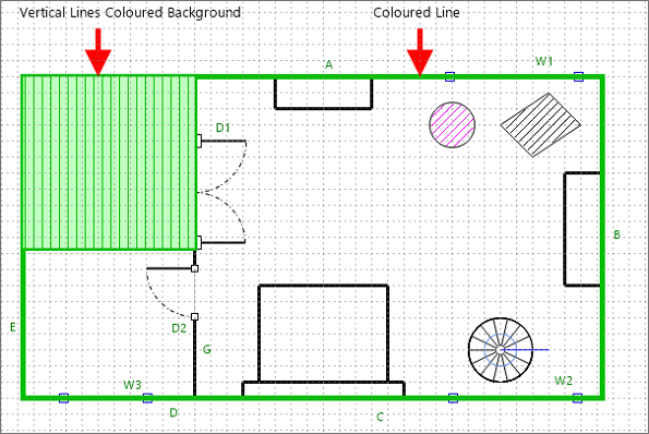
The following drop-down menu lets you select a background, such as horizontal lines, vertical lines, or straight cross, among others (see the example floorplan, below).
--->---> The following floorplan shows how both the selected background and coloured line are inserted on the sketch.
While working with the Tools button, , you can also edit the components (wall, door, window, stair, rectangle, arrow, etc.) and texts that you have inserted on your sketch.
1.B.5 Modifying a Component
1. Right-click on the component that you want to modify (e. g., a Right Door) to display the Edit window.
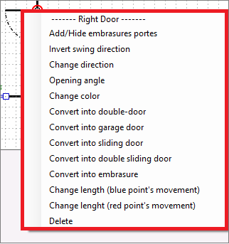
2. Click on the option that best suits your needs.
The selected component will be modified immediately.
1.B.6 Modifying a Text
1. Right-click on the text that you want to modify (e. g., a Lead Exposure text) to display the Edit window.
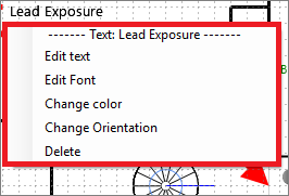
2. Click on the option that best suits your needs.
The selected text will be modified immediately.
2. Text Button
The  button allows you to identify the various parts of the floorplan.
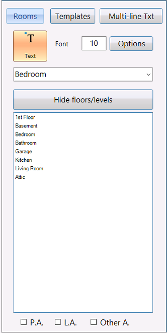
2.A Displaying Rooms
- The
 button displays the List of Rooms previously added on Field Section> List of rooms tab.
- 1. To select a room, just click on it or select it from the upper drop-down menu.
2. Click on the desired area of the floorplan to insert the room's name and then, begin your drawing.
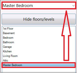
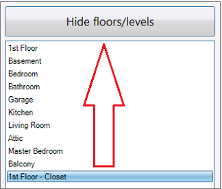
2.A.1 Hiding Floors/Levels
-
- If you added a room via Field Section> List of rooms tab (let's say 1st Floor - Closet), and you only want to display the name of the room instead of its full name, click on the following button:

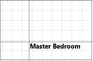
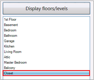
The room's level will disappear, as shown below:
2.B Inserting a Template
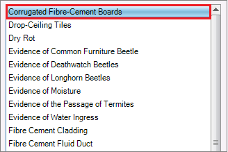
1. Click on  to display the List of Templates (see below).
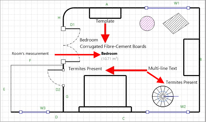
2. Select the template that best suits your needs (for example, Corrugated Fibre-Cement Boards).
3. Click on the sketch to introduce the template's name.
4. Click on to display the List of rooms and select the room you want to work with.
5. Click on the plan to insert the rooms' name along the template's description (see the example floorplan, below).
2.B.1 Adding a Template
1. Introduce the template's name in the available text field.
- 2. Click on
 .
.
The new template will be added at the bottom of the List of templates.
2.C Inserting a Multi-line Text
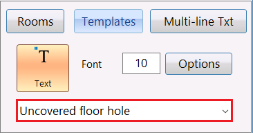
1. Click on  to open the following window.
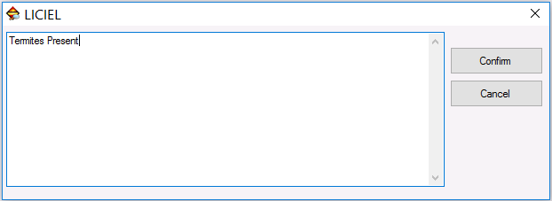
2. Enter the desired text.
3. Click on  to save it. To cancel the operation, click on
  .
.
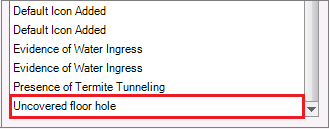
After saving it, the text will be added to the List of Templates.
4. Click on the plan to insert it as much as necessary (see the example floorplan, below).
2.D Choosing the Font Size
Enter the desired size in the 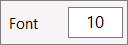 text field.
2.E Choosing Other Font Attributes
1. Click on  to open the Font window.
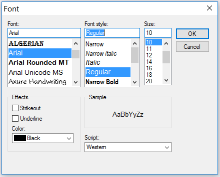
2. Select the desired font, font style, size, effects, color, and the script to be used on your floorplan.
3. Click on  to save your selections. To clear them, click on
  .
.
Back on the Text button's functions.
2.F Inserting a Room's Measurement
Note: The room's measures must be first determined in the Area Computing Module for they to appear in this section.
1. From the List of rooms, select the room you want to work with.
2. Check one of these 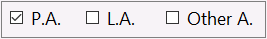 boxes to insert the selected room's measurement for the Private Area, the Living Area, or Other Area.
Both the room's name and the code for the selected area will appear in the top text field.
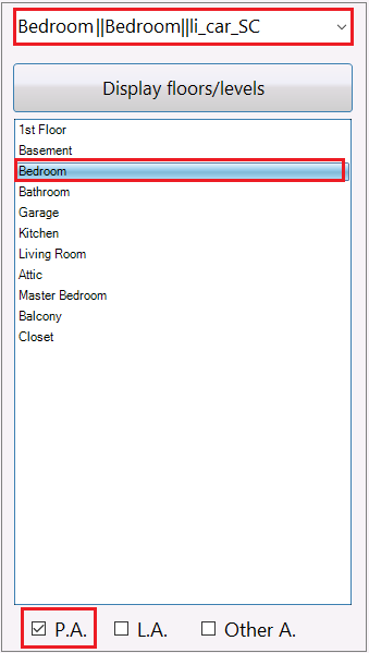
3. Click on the sketch to insert it (see the example floorplan, below).
 .or .
.or .
--->---> The following floorplan shows how the selected template, the room's measurement, and the multi-line text are inserted on the sketch.
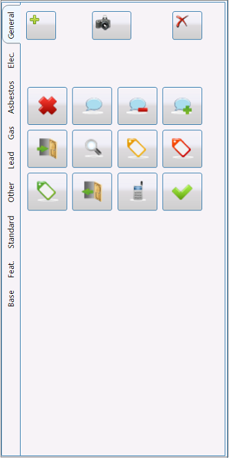
3. Images Button
The  button allows you to add images/icons to your floorplan.
|
|
The tool includes the following sub-tabs:
|
- 3.A General Sub-tab
- 3.A.1 Uploading/Resizing/Inserting an Image
1. Click on  to upload the image from your computer.
The uploaded image will display in the following window.
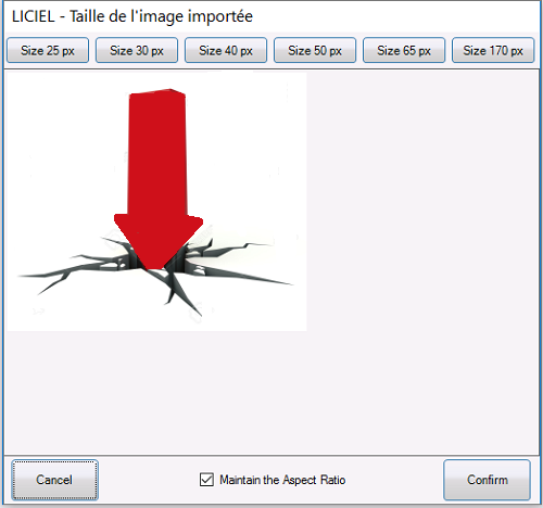
- 2. Use the upper buttons to resize your image.
3. Keep the box checked if you want to keep the default ratio. Otherwise, uncheck it.
 - 4. After sizing the image, click on
 .
.
 .
. | The uploaded image will be converted into an icon and will be added to the default ones. |
|
|
| 5. Click on the image. 6. Click on the desired area of the plan to insert it (see the example floorplan, below). |
3.A.2 Adding Images from your Computer
1. Click on  to take a picture from your webcam.
2. Continue with the steps explained in the previous section.
- 3.A.3 Deleting Images/Icons
|

Note: Make sure that you really want to delete an image/icon, since a confirmation/countdown pop-up window will not open for you to confirm or cancel the deletion.
3.A.4 Inserting Default Icons
The General sub-tab buttons allow you to insert defaults icons on your floorplan as needed. Feel free to assign them the meaning that best suits your needs.
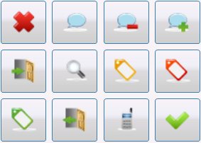
1. Click on the icon that you want to add.
2. Click on the desired area of the plan to insert it.
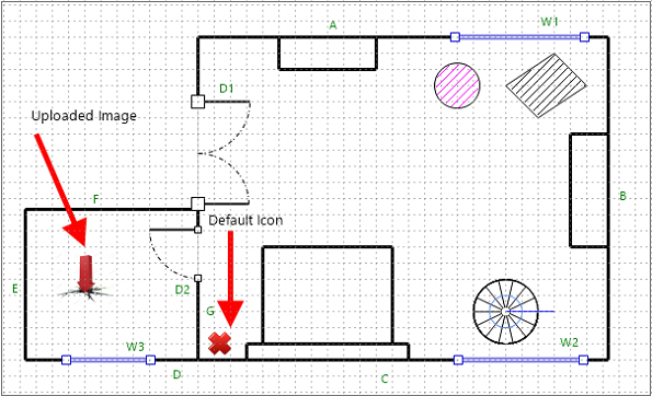
--->---> The following floorplan shows how both the uploaded image and the default icon are inserted on the sketch.
3.B Electricity, Asbestos, Gas, Lead, and Other Sub-tabs
Note: The principles of the General sub-tab are the same than the Electricity, Asbestos, Gas, Lead, and Other sub-tabs. The only difference is the Asbestos and Lead sub-tabs will show some parameters (see explanation below) if you add them when working on the Asbestos Inspection and Lead Exposure Risk Assessment modules.
Use the different sub-tabs and default icons according the job(s) you are working with (Home Inspection, WDO Inspection, Lead Exposure Risk Assessment, etc.).
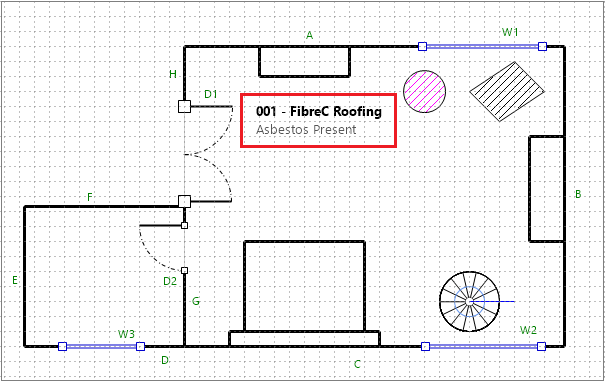
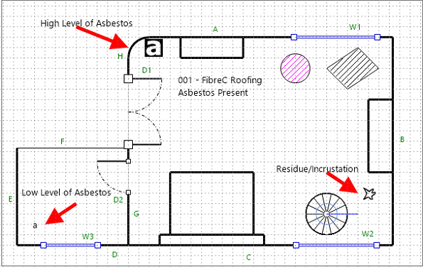
3.C Asbestos Sub-tab
|
|
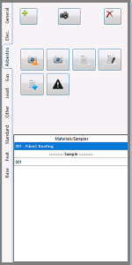
The Asbestos sub-tab allows you to add the results of the Asbestos Inspection to your floorplan. Material(s) analyzed during the inspection will be listed in the Materials/Samples section, while the sample's number will appear in the Sample section. |
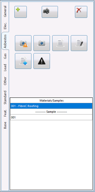
3.C.1 Inserting the Asbestos Inspection Data on the Floorplan
1. Create a floorplan and assign it a name (e. g., Bedroom).
2. Open the Asbestos Inspection Module and add this room to the List of Visited Room if you have not been yet created it.
3. Introduce the Asbestos Inspection data for the selected room and add it to the report.
--->--> See the WikiLICIEL "Asbestos Inspection Module" article for more info.
4. Back on the Floorplan Drafting/Sketching Module, Asbestos sub-tab, click on the data that you need to insert.
5. Click on the desired area of the plan to insert it (see the example floorplan, below).
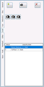
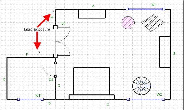
3.D Lead Sub-tab
|
|
The Lead sub-tab allows you to add the results of the Lead Exposure Risk Assessment to your floorplan. The Reading number will be listed in the Values section, while the lead-exposed components will appear in the Lead-Positive Elements section. |

3.D.1 Inserting the Lead Inspection Data on the Floorplan
1. Create a floorplan and assign it a name (e. g., Bedroom).
2. Open the Lead Exposure Risk Assessment module and add this room to the List of Visited Room if you have not been yet created it.
3. Introduce the Lead Inspection data for the selected room, add the Reading value and save it.
--->--> See the WikiLICIEL "Lead Exposure Risk Assessment" article for more info.
4. Back on the Floorplan Drafting/Sketching Module, Lead sub-tab, click on the data that you need to insert.
5. Click on the desired area of the plan to insert it (see the example floorplan, below).
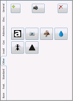
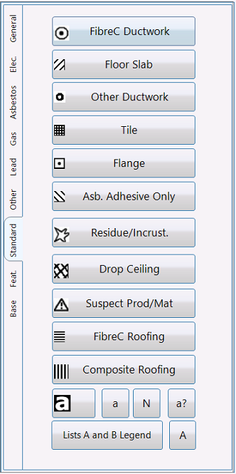
- 3.E Standard Sub-tab
|
|
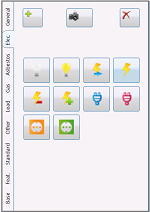
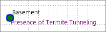
The Standard sub-tab allows you to indicate the presence of the following elements:
It also allows you to indicate the presence of the asbestos and edit the showed captions. |
3.E.1 Inserting an Element
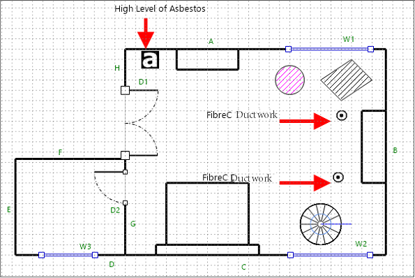
1. Click on the element that you want to add (fo rexample, FibreC Ductwork).
2. Click on the desired area of the plan to insert it (see the example floorplan, below).
3.E.2 Indicating the Presence of Asbestos

The "a" button means High Level of Asbestos.
The "a" button means Low Level of Asbestos.
The "N" button means Non-Asbestos.
The button "a?" means Susceptible.
1. Click on the symbol that you want to add (for example, High level of asbestos).
2. Click on the desired area of the plan to insert it (see the example floorplan, below).
- 3.E.3 Editing the Symbols Caption
1. Click on  to open a Photo Paint window. to open a Photo Paint window. |
| g |
|
|
| 2. Edit the showed captions as needed. |
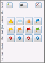
3.F Features Sub-tab
|
|
The Features sub-tab shows you images of the different facilities that you can insert on the floorplan. The Scale drop-down menu allows you to select the size of these facilities.
|
3.F.1 Inserting a Facility
1. Click on the facility that you want to add.
2. Select its size by using the Scale drop-down menu.
3. Click on the desired area of the plan to insert it (see the example floorplan, below).
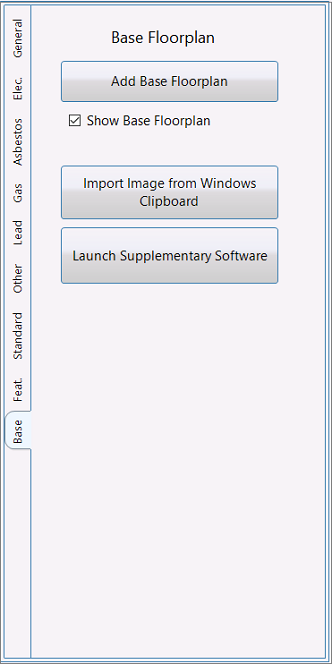
3.G Base Sub-tab
|
|
The Base sub-tab gives you the possibility of using a diagram, which can be considered as a base floorplan, and then make different layers relating to your different inspections. |
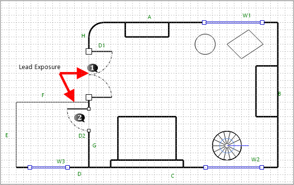
Let's say that you have a diagram (maybe a floorplan provided by your client about a previous Lead Exposure Risk Assessment) and you want to use it as a base to make an sketch about your Asbestos Inspection.
1. When starting to work on your Asbestos Inspection sketch, click on  to access to the File's Plan folder in your hard drive.
2. Select the base floorplan that you want to use (in the example, the Lead Exposure Risk Assessment diagram) and upload it.
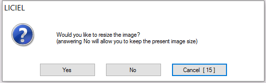
The Resizing Image window will appear (see below). If you click on the Yes button, the image's size will be adapted to the one of the diagram you are working with; then, the image will automatically be inserted in the Drawing Area. If you click on the No button, the sketch will keep its original size, and you will have to click on the Drawing Area to insert it.
|
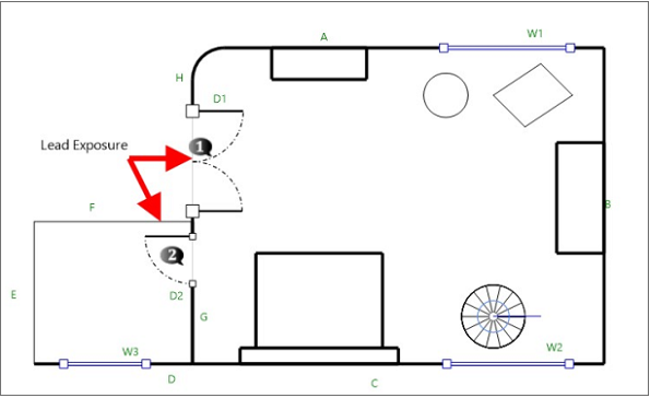
In both cases, you will visualize your base floorplan and will note that the Drawing Area grids disappeared. |
To make visible or hide the selected base floorplan, check/uncheck the  box, respectively.
You can also move your mouse over the Drawing Area to visualize it.
The idea is that the base floorplan serves you as a visual guide to make your diagram, which should looks like as follow after inserting on it the asbestos results:
The Base sub-tab also allows you to import screenshots from your clipboard and work with an additional software.
3.G.1 Importing Images from the Windows Clipboard
1. Capture the image that you want to import.
2. Click on 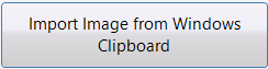 .
.
The Resizing Image window (shown above) will appear for you to resize the screenshot.
3. Click on the plan to insert it.
3.G.2 Working with a Supplementary Software
Click on  .
.
The software must be installed on your computer for you to complete this action.
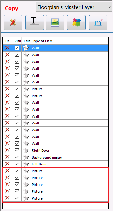
4. Layers Button
The  button gives you access to the List of Components (elements and texts) that you have inserted into your floorplan. It also allows you to manage them as needed.
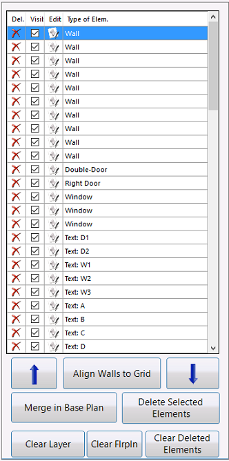
4.A Deleting an Element/a Text
1. On the List of Components, click on the element/text that you want to remove.
2. Click on the  box beside the selected element/text.
A confirmation/countdown pop-up window will appear.
3. Click on the Yes button to confirm the action, or on the No button to cancel it.
The selected element/text will disappear immediately.
4.B Hiding/Showing an Element/a Text
1. On the List of Components, click on the element/text that you want to hide.
2. Uncheck the  box beside the selected element/text (e. g., a Double Door).
It will hide as shown in the sequence below.
To make it visible again, just check the  box.
box.
It will appear on the floorplan, as shown below.
4.C Editing an Element/a Text
1. On the List of Components, click on the element/text that you want to modify (e. g., a Double Door).
2. Click on the  box beside the element/text to display the Edit window.
- 3. Click on the option that best suits your needs, then go to the floorplan you are working with and modify it.
- The changes will be visible immediately.
4.D Sorting an Element
1. On the List of Components, click on the element that you want to sort.
2. Click on the blue arrows  to move it up or down on the list.
4.E Aligning a Wall to the Grid
1. On the List of Components, click on the wall that you want to align.
2. Click on 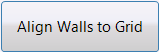 .
.
The selected wall will automatically be aligned to the grid.
4.F Merging in Base Plan
This tool is very useful if you want to share a floorplan's components with other diagram(s).
1. To do so, select the floorplan you want to work with (e. g., the WDO Inspection sketch).
2. Click on  .
.
The selected floorplan's components will be hidden from the List of components.
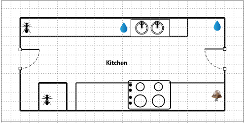
3. From the Copy drop-down menu, select the diagram you want to receive the components (e. g., the Floorplan's Master Layer sketch).
You will notice that the components that you just shared were added to the bottom of the selected diagram's List of components,
And they also appear in the selected sketch.
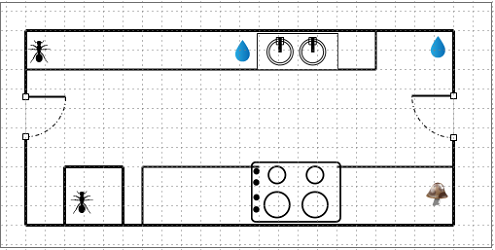
4.G Deleting Selected Elements
1. From the List of components, click to highlight the component that you want to remove (e. g., a text).
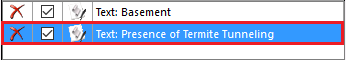
- The component will be marked in the floorplan as follow:
2. Click on  .
.
A confirmation/countdown pop-up window will appear.
3. Click on the Yes button to confirm the action, or on the No button to cancel it.
After confirming the operation, the removed component will appear in orange.
4.H Clearing Layer
To remove all components from the selected floorplan, click on  .
.
Note: Make sure that you really want to delete the entirety of elements, since a confirmation/countdown pop-up window will not appear for you to confirm or cancel the deletion.
4.I Deleting the Floorplan
1. Click on  .
.
A confirmation/countdown pop-up window will appear.
2. Click on the Yes button to confirm the action, or on the No button to cancel it.
4.J Clearing the Deleted Elements
1. Click on  .
.
A confirmation/countdown pop-up window will appear.
2. Click on the Yes button to confirm the action, or on the No button to cancel it.
After confirming the operation, all of the elements previously removed and marked in orange will disappear from the List of components.
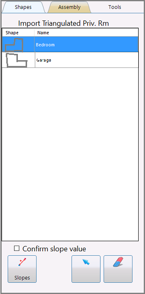
5. Area Computing Button
The  button allows you to import areas that you would have previously triangulated in the Surface Area Computing Module, so you can make assemblies (manual and assisted) to build your floorplan faster.
The tool includes the following tabs:
-
Shapes
-
Assembly
-
Tools
5.A Shapes Tab
|
|
The Shapes tab gives you access to the Import Triangulated Private Rooms section. It also allows you to measure the rooms, rotate them and delete parts of them, if necessary. |
|
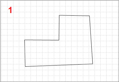
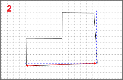
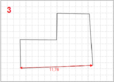
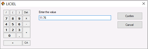
5.A.1 Inserting a Triangulated Room 1. Select the triangulated room that you want to add from the Import Triangulated Private Rooms section. 2. Click on the Drawing Area to insert it (see the first floorplan on the right). 5.A.2 Confirming the Slope Value Check the 5.A.3 Measuring Parts of the Room 1. Click on 2. Mark the distance between any two points that you need to measure (see the second floorplan on the right). A LICIEL window will appear for you to introduce the value. You can enter it manually or use the keypad on the left. 3. Click on To cancel the operation, click on The value that you just entered will be inserted in the selected part of the room (see the third floorplan on the right). |
   |
 box to set the slope value.
 .
.
5.A.4 Rotating a Room
1. Click on  .
.
2. Click on the sketch, then click on this  icon and rotate the room as needed.
5.A.5 Deleting Parts of a Room
1. Click on  .
.
2. Click on each part of the room that you want to delete.
5.B Assembly Tab
|
|
The Assembly tab allows you to manually assemble the triangulated rooms and connect them, if necessary. |
5.B.1 Manual Assembly Section
1. Click on  to enable the
  button from the Buttons Section.
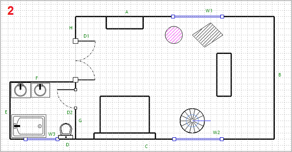
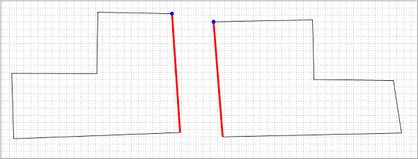
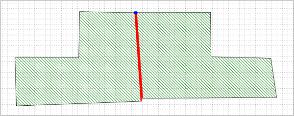
2. Click on the part of the room that you want to modify (e. g., a wall that needs to be moved - see the example floorplan, below).
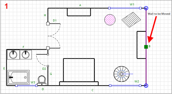
3. Make the changes as needed (see the example floorplan, below).
5.B.2 Assisted Assembly Section
Click on  to display the WikiLICIEL "Floorplan Drafting/Sketching Module" article.
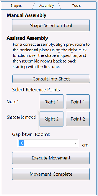
5.B.3 Select Reference Points Section
This section allows you to connect two or more triangulated rooms in order to create a floorplan (see section "5.B.4 Connecting Triangulated Rooms").
The Gap Between Rooms drop-down menu allows you to indicate the rooms spacing in centimeters.
The Execute Movement and Movement Complete buttons allow you to finish the connection between two or more triangulated rooms, as explained below.
- 5.B.4 Connecting Triangulated Rooms
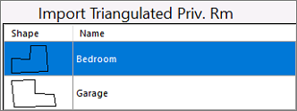
1. On the Shapes tab, select the rooms that you want to connect.
2. Click on the Drawing Area to insert them, one by one.
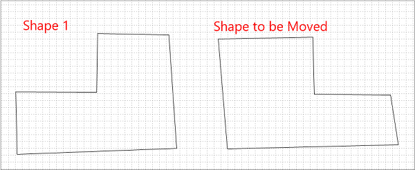
3. Determine which is the Shape 1 and which is the Shape to be Moved.
4. On the Assembly tab, click on  , then click on a reference line of the Shape 1 where you want the connection to be established.
The reference line will turn red, as shown in the example floorplan, below.
5. On the Assembly tab, click on  , then click on a reference point of the Shape 1 where you want the connection to be made.
The reference point will turn blue, as shown in the example floorplan, below.
6. Repeat the same process with the Shape to be Moved, by first clicking on  and then, clicking on
  .
.
7. On the Assembly tab, click on  to connect the rooms.
8. Click on  to save the changes, then continue with the creation of your floorplan.
5.C Tools Tab
|
|
The Tools tab allows you to measure new rooms, and includes the following sub-tabs:
|
5.C.1 Tools Sub-tab
5.C.2 Measuring a Room
1. Click on  to display the following window:
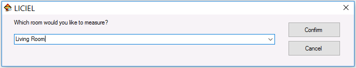
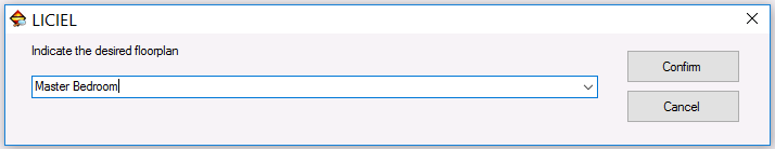
2. Enter the name of the room that you need to measure (e. g., Living Room).
3. Click on . To cancel the operation, click on .
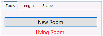
The room's name that you entered will appear in red on the Tools sub-tab, as shown below, while a blank Drawing Area will display for you to create the floorplan.
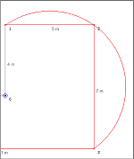
4. Click from one point to another one in the Drawing Area to start drawing your sketch and open the Surface Area Data Entry window.
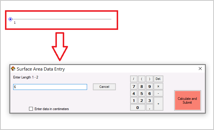
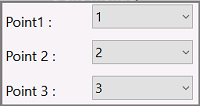
4. Introduce the length between the two points (by default, Length 1-2) in the text field. You can also use the keypad on the right.
If you want to take the measurement in centimeters, check the Enter data in centimeters box. To cancel the operation, click on  .
.
5. Click on  .
.
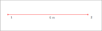
The length that you just entered will be inserted in the floorplan, as shown below.
6. Repeat the process of entering the length for the rest of the points (2-3, 3-4, 4-5, etc.) until finishing the sketch.
7. Click on  to ...
8. Click on  to enable the option of selecting three arc points in order to create an arc.
9. Click on  .
.
10. Click on  to indicate the presence of an obstacle, if any.
11. Click on  to save all changes.


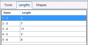
5.C.3 Lengths Sub-tab
This sub-tab summarizes the lengths and their names.
5.C.4 Shapes Sub-tab

This sub-tab summarizes the shapes previously created.
III.B Buttons Section

Use the following buttons to manage the floorplans as follow:
 to open the New Floorplan window for you to create/duplicate/customize/import a diagram.
 to stay on the right-click mode. Practical for field use on tablet, for example.
 to center the floorplan in the Drawing Area.
 to optimally reframe the Drawing Area.
 to select the zoom multiplier.
 to delete the last component.
 to reset the removed component.
 to select all reference points on the floorplan.
 to show/hide the Drawing Area grids and to magnetize the cursor.
- to make changes on the sketch. See section "5.B.1 Manual Assembly".
 to open the Floorplan Settings window.
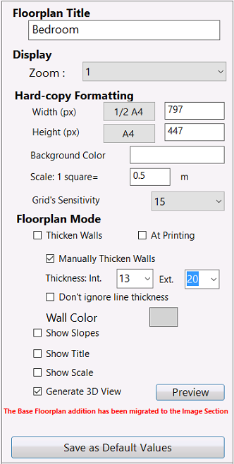
III.B.1 Modifying a Title
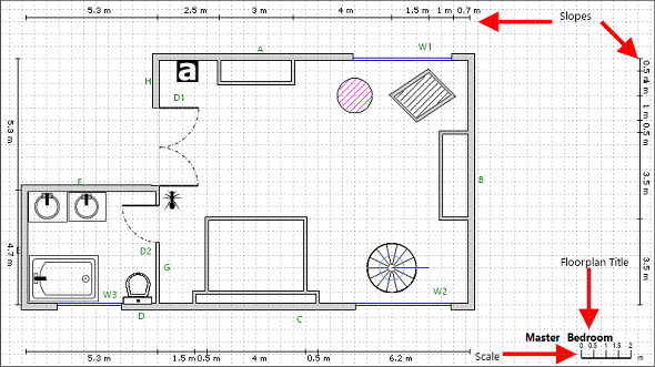
The Floorplan Title section shows the title of the floorplan that you created. You can modify it, if necessary.
1. Click on the Floorplan Title text field to display the Edit window.
2. Enter the new room's name.
-
- 3. Click on . To cancel the operation, click on .
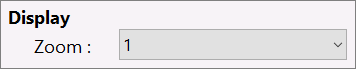
The Display drop-down menu allows you to select the zoom multiplier levels.
III.B.3 Modifying the Floorplan Size
The Hard-copy Formatting section shows you the size of your sketch in both paper sizes and pixels.
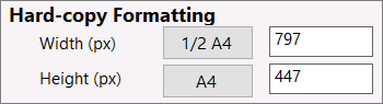
1. To modify these values, click on the Width and/or Height text fields to display the Edit window.
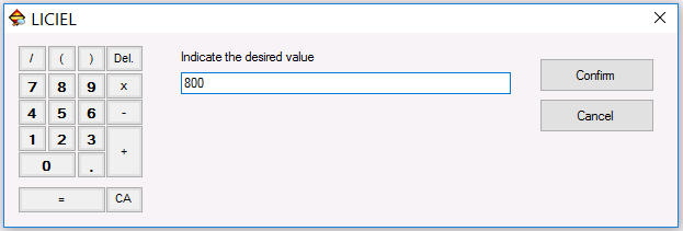
2. Introduce the new size. You can enter it manually or use the keypad on the left.
3. Click on . To cancel the operation, click on .
The new size will appear in the selected field.
III.B.4 Selecting a Background Color
1. Click on the  field to display the Color Selector window.
-
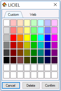
2. Select the color on the Custom or Web tabs.
-
3. Click on
to save your selection. To clear it, click on . To remove it, click on .
-
The
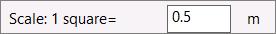 section shows the default scale used on your floorplan.
1. To change it, click on the Scale text field to display the Edit window (shown above).
2. Introduce the new scale. You can enter it manually or use the keypad on the left.
3. Click on . To cancel the operation, click on .
The new scale will appear in the Scale text field.
III.B.6 Modifying the Grid's Sensitivity
The 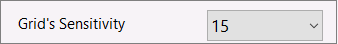 drop-down menu allows you to adjust the size of the tiles of the grid, which is 15 by default.
III.C Floorplan Mode Section
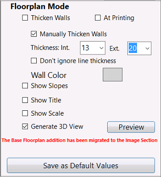
III.C.1 Thicken Walls
The  box allows you to automatically make thicker all of the walls and most components of your floorplan, as shown below.
III.C.2 At Printing
The  box allows you to include the thick walls when printing the floorplan.
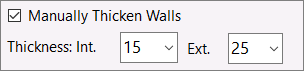
III.C.3 Manually Thicken Walls
The Manually Thicken Walls box works in conjunction with both the Thickness: Interior and Exterior drop-down menus.
They allow you to manually set the thickness of both the Interior and Exterior walls.
III.C.4 Don't Ignore the Line Thickness
The  box allows you to keep the thickness walls configuration for walls and most of components of your diagram.
If you only want to keep the thickness for the walls, you must first uncheck this box.
III.C.5 Wall Color
The  field gives you access to the Color Selector window for you to select the color of the walls (see explanation above).
III.C.6 Show Slopes, Show Title, Show Scale
These checkboxes  allow you to show/hide the Slopes, the Floorplan Title, and the Scale on your floorplan.
III.C.7 Generating a 3D View
The 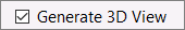 box works in conjunction with the
  button. They both allow you to create a three-dimensional view of your floorplan.
1. Check the Generate 3D View box.
2. Click on the Preview button to open the Viewer 3D window.
The 3D view will be generated immediately.
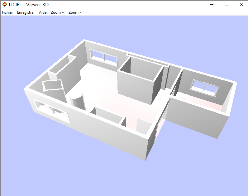
On the Viewer 3D window:
The Save button allows you to save your three-dimensional floorplan on the File's Photos folder in your computer.
The Help button opens the following window, which explains how to manage the 3D floorplan by using both the mouse and your computer keyboard.
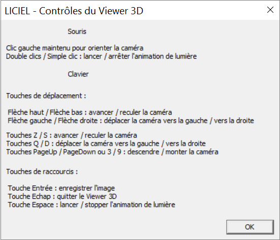
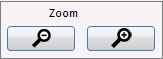
The Zoom + and Zoom - buttons allow you to maximize and minimize the 3D image as needed.
Back on the Floorplan Settings window.
To save the changes, click on  .
.
Back on the Buttons Section.
 provides access to the Settings Tools window.
<span id="result_box